With the rapid growth of the automobile industry and the rising standard of living, consumers are no longer solely focused on price when purchasing a vehicle. Instead, they increasingly prioritize the overall quality and performance of the car. This shift in consumer demand has pushed automotive manufacturers to continuously innovate, introducing new models and gradually upgrading the design of vehicles to better meet market expectations.
After the launch of a particular car model, it quickly gained popularity due to its excellent "value for money" ratio. Initially, there was a high demand, making it difficult to find available units. However, as more people started using the car, some industry insiders began to voice higher expectations regarding the model's specifications. Consumers pointed out that for mid-range cars, the current front knuckle assembly uses an older hub unit structure with a slightly lower gear ratio, which limits overall performance and fails to fully satisfy market needs. As a result, many hoped that the manufacturer would enhance and optimize the product further.
In response to the design requirements from the automobile company, we decided to apply CAD/CAE technology to optimize the design and conduct detailed analysis of the front knuckle assembly. The goal was to improve the performance of the front knuckle and elevate the product’s overall grade, ultimately meeting both vehicle and user demands more effectively.
**Determination of the Improvement Plan**
It is important to note that the front knuckle assembly consists of several components, including the front knuckle and the front hub unit. When considering structural optimization, the front knuckle itself is passively affected by the upgraded hub unit. Since the changes to the knuckle have minimal impact on its performance, this paper will focus primarily on the structural optimization and analysis of the front hub unit. The improvement of the steering knuckle will not be discussed in detail here. Additionally, during the CAE process, certain fine structures can be simplified or omitted in 3D modeling to facilitate mesh division in finite element analysis without significantly affecting the overall results.
**1. Analysis of the Current Front Hub Unit Structure**
The existing front hub unit, as shown in Figure 1, has the following characteristics:
- The service life of the bearing is not only dependent on the bearing's quality but also on how well it fits with the front knuckle and flange. Any oversight during assembly could lead to early failure.
- In the current design, the bearing is influenced by tolerances in mating parts, resulting in a large clearance after press fitting, which may cause inconsistent performance.
- The existing bearing offset (ideally close to zero) is relatively large, negatively impacting the bearing's lifespan.
**2. Improvement Plan**
Based on the shortcomings of the current structure, the optimization principle and goal were set: adjust the internal structure of the hub unit to ensure the bearing's dynamic load capacity and lifespan while keeping the assembly dimensions as consistent as possible.
Taking into account the application of the hub unit in the front knuckle assembly and related technical specifications, along with past experience and similar product designs, the optimized front hub unit structure is illustrated in Figure 2.
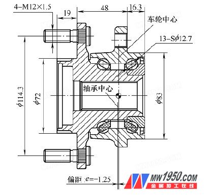
Figure 2 Optimized Front Hub Unit
PVDF Head Solenoid Dosing Pump
*Strong stability: working stability in AC 100-240V, and suitable for the range of 50-60Hz
* High protection level: protection level reached to IP65, it allowed pump to provide safe services at severe operaton condition
*Ball check valves: it through double valve ball, seat and sleeve to form the sealing system, that enhance the precision
*Compact size: small, quiet and stable
operation
*High speed operation: high measurement precisions, up to 360 strokes per minute which eliminate the pulsation effect.
*Durable diaphragm: the diaphragm is made by PTFE, which is
compatible with all kinds of chemicals. In typical use, the diaphragm
can last up to five years, which 5 times as national standard
GB/T7782-2008
*Several types: manual control or automatic control, the
automatic control can divided to: 4-20mA electric current signal
control, digital impulse signal feedback control, digital impulse
feedback control with Rs485 communication interface, 4-20mA electric
current signal control with Rs485 communication
interface.
*Percentage adjustment: local adjust percentage for stroke
and frequency
0~100%
*Level monitor, low-level shutoff with alarm output
Pvdf Head Solenoid Dosing Pump,Pvdf Head Chemical Dosing Pump,Pvdf Head Dosing Metering Pump,Pvdf Head Solenoid Diaphragm Metering Pump
Zhejiang Ailipu Technology Co., Ltd. , https://www.alipu.com