1. Analysis of the Rolling Process for Thin-Walled Rotating Parts
In a research project conducted by the company's head office research institute, the product components included thin-walled rotary shell parts such as housings and cylinders (see Figures 1 and 2). These parts are challenging to process due to their thin walls and complex shapes.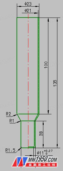
Figure 1: Housing
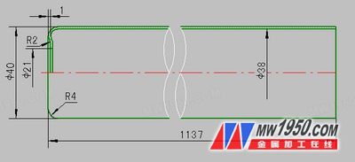
Figure 2: Cylinder
2. Rolling Process Method for Thin-Walled Rotating Parts
After extensive brainstorming and careful planning, the following steps were established for the rolling process: **Step 1:** Preliminary design and machining of the rolling positioning mandrel based on the internal dimensions from the product drawings. **Step 2:** Cutting the raw material according to the preliminary calculated blank length. **Step 3:** Conducting process tests on the lathe. After several rolling operations, the final positioning mandrel (as shown in Figures 3 and 4) and the pre-processing part length were determined (the housing was 124mm, and the cylinder was 1,145–1,150mm).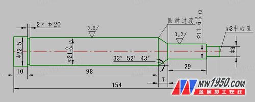
Figure 3: Spinning Shell Mandrel
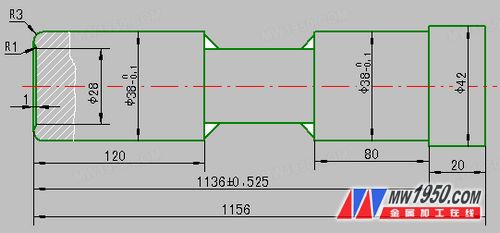
Figure 4: Spinning Cylinder Mandrel
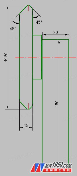
Figure 5: Roller Wheel
3. Conclusion of the Rolling Process for Thin-Walled Rotating Parts
Within less than a month, the research and production tasks for both the housing and cylinder parts were successfully completed, meeting all design requirements. Although some adjustments are still needed for optimal performance, this process set a new precedent for rolling thin-walled shells using a roller. It fulfilled the needs of the research and ensured smooth progress in both development and production, achieving the expected design outcome.Naipu QJ Series are vertical multi-stage submersible pumps designed for pumping clean water from deep wells, rivers, reservoirs and mines etc., as well as applications in industrial water supply , agricultural irrigation projects. Fire fighting and so on. QJR is specially designed for geothermal applications featured by heat-resisting, anticorrosion and anti-aging properties, water temperature up to 90℃.
Typical Applications---
Water drawing tool submerging into water to work
Drawing the groundwater from the deep well
Drawing engineering of rivers reservoirs, channels, and soon
Irrigation of farmland
Solar submersible
NP-QJ Deep Well Pump Configuration Drawing
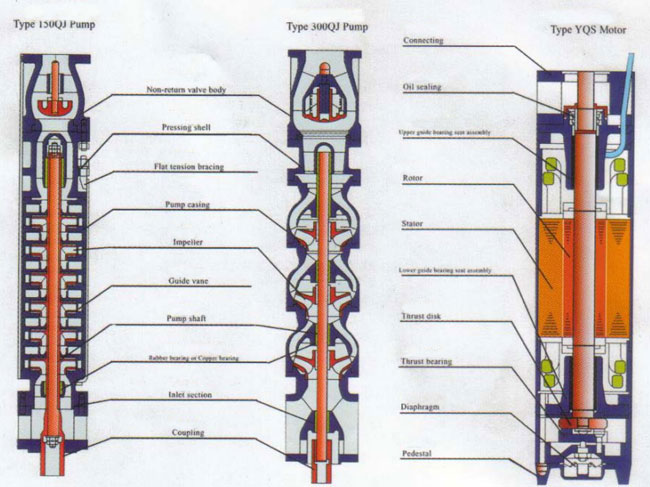
Main Part Number At The Drawing
|
1. Pump casing
2. Pump Cover 3. Impeller 4. Shaft 5. Wear Ring 6. Impeller Cap |
7. Braking Pad
8. Shaft Sleeve 9. Packing Gland 10. Seal Cage 11. Packing 12. Cantilever Bearing Assembly |
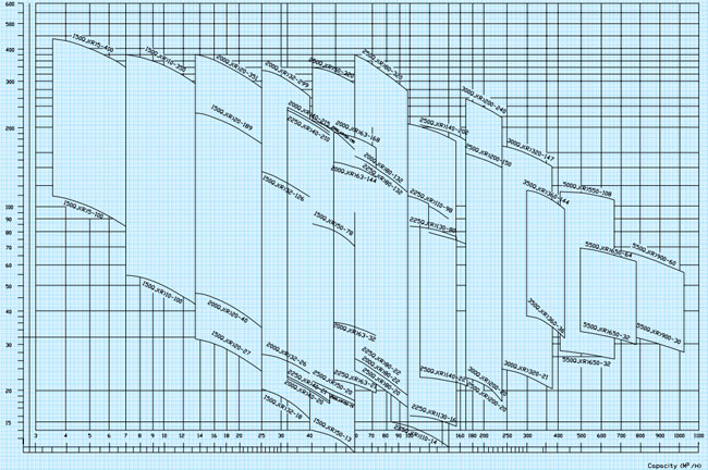
QJ DEEP WELL PUMP SELECTION CHART
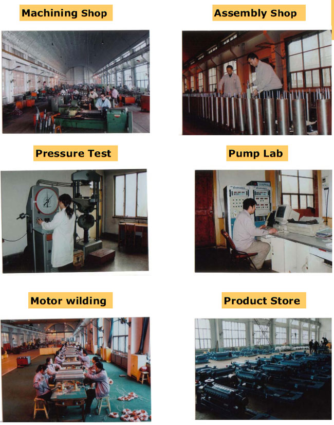
NP-QJ DEEP WELL PUMP WORKSHOP SHOWING
Deep Well Water Pumps,Deep Well Pump,Deep Well Bore Pump,Vertical Submersible Water Pump
Shijiazhuang Naipu Pump Co., Ltd. , https://www.naipu-pump.com